

Switchgear Tulip Contact Manufacturer: Precision Components for Reliable Switchgear Performance
2026-10-02
Every switchgear assembly counts on tiny components to handle massive electrical loads. The tulip contact is one such precision part—its ability to maintain a clean, low-resistance connection directly determines system reliability. At MOLDVOLT, we combine advanced manufacturing with rigorous testing to produce tulip contacts that excel under demanding conditions. In this article, we break down the engineering behind our contacts and why they matter for long-term switchgear performance.
Why Tulip Contact Geometry Shapes Arc Interruption
Arc behaviour in a breaker is largely dictated by where the root lands and how fast it moves. Tulip contacts use several independent fingers, so the current flow through each finger produces local magnetic forces that push the arc sideways and keep it rotating. This rotation continuously stretches the plasma column, increasing its resistance and helping the arc extinguish near a natural current zero.
With plain flat contacts the arc tends to sit in one crater, burning the same metal and leaving a hot spot that can reignite. The tulip arrangement avoids that by spreading the damage and repeatedly presenting cooler surfaces. It also keeps the arc away from the nozzle, so gas flow stays focused on cooling rather than being choked by metal vapour.
Material Selection for Contacts That Outlast the Breaker
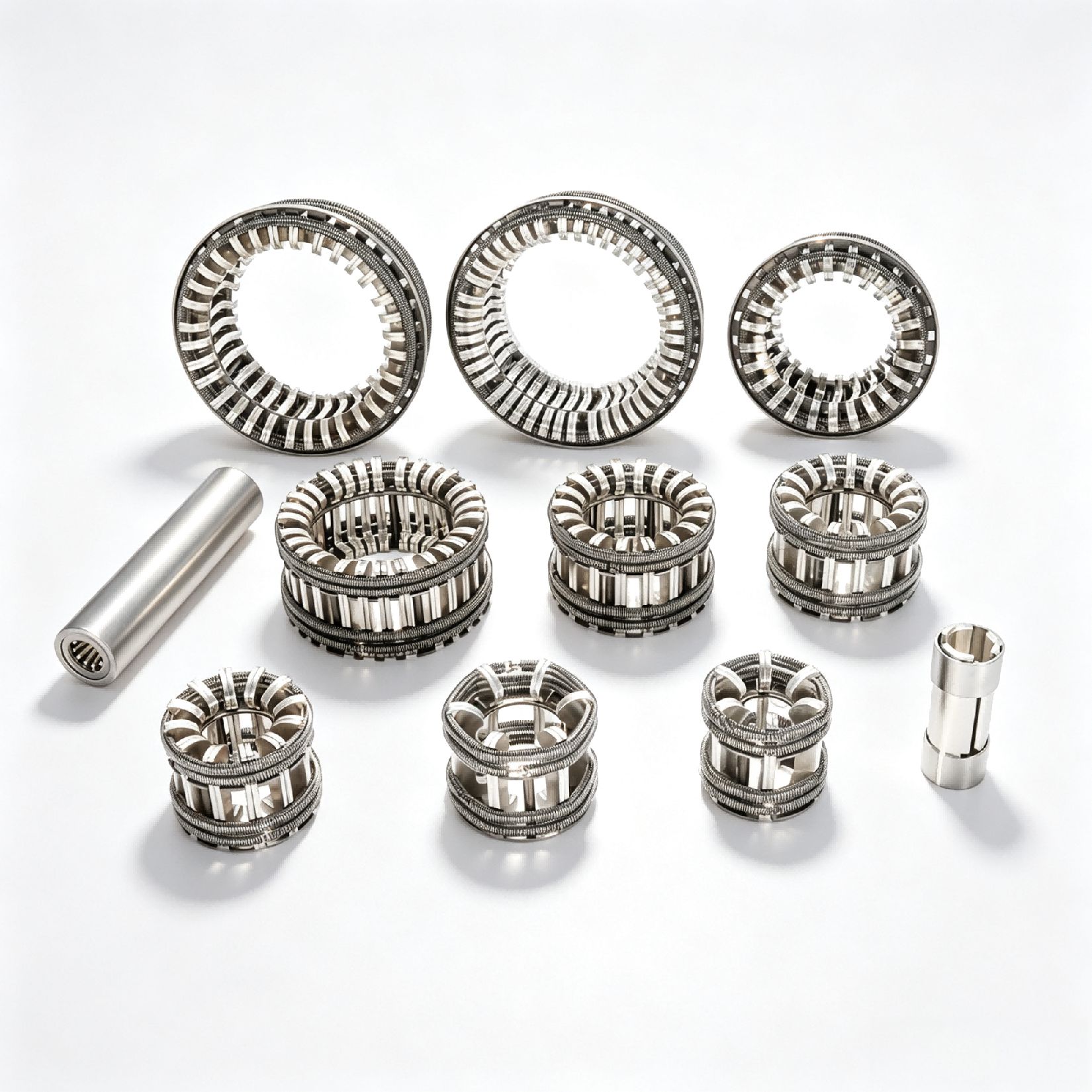
Contacts often fail long before the mechanism does, so the real question is which material can shrug off arcing without turning brittle or welding shut. Silver-tungsten and silver-tungsten-carbide composites remain the go-to choices for high-current breakers because the refractory metal skeleton absorbs arc heat while the silver carries current. A 50/50 weight ratio works for many mains applications, but shifting to 35% silver improves arc erosion resistance when interruption duties get violent. The trade-off is slightly higher resistance, yet that's usually less troublesome than a contact that craters after a few thousand operations.
What separates a decent contact from a great one is how it handles repeated thermal shock at the surface. Fine-grained silver-nickel alloys suppress material transfer in moderate-duty breakers, preventing the classic pip-and-crater pattern that increases contact resistance. For sliding or wiping contacts, silver-graphite adds a dry lubricating effect that keeps friction low even after oxidation builds up. The graphite content typically ranges from 2% to 5%, and pushing beyond that sacrifices too much arc resistance for the sake of smoothness.
Manufacturing route matters as much as raw composition. Press-and-sinter methods leave a controlled porosity that helps channel arc gases away from the contact face, while infiltration produces a denser part better suited to repeated mechanical impact. Some shops over-spec hardness and end up with contacts that crack under thermal stress; others chase conductivity and watch contacts erode in weeks. Field data from breaker replacements consistently shows that a tailored material - not the catalog default - adds more usable cycles than any beefed-up mechanism ever will.
Holding Tight Tolerances on Tulip Finger Assemblies
Holding tight tolerances on tulip finger assemblies is less about chasing a single number and more about controlling a stack-up that begins with raw stock and follows the part through every heat treat and grind cycle. The three fingers need to share load evenly, so slight differences in length, radius, or angular spacing quickly show up as uneven wear or noise in the joint. Getting there means the process has to be stable enough that a 0.01 mm deviation is caught early, not discovered after the parts are already sitting in a bin.
Distortion after case hardening is the usual culprit when tolerances drift. Even a well-machined tulip finger can move enough during quenching to fall out of spec if the hardening cycle isn't matched to the part geometry. A practical approach is to leave a controlled amount of stock on critical surfaces before heat treat, then finish grind in a sequence that alternates between fingers. That spreads out the stress relief and keeps the whole assembly from bending toward one side.
The final check should not be a simple pass/fail on isolated diameters. Runout matters just as much as size because a finger with perfect diameter but excessive runout will still create a tight spot when the assembly rotates. For that reason, the best inspection routines gauge the three fingers as a set, often with a reference fixture that mimics the mating rollers. Only then do the individual tolerances translate into a joint that feels smooth and stays quiet over time.
Preventing Contact Welding in High Fault Current Conditions
High fault currents can cause contact welding in switching devices, leading to permanent closure and potential system failure. This occurs when the localized heating at the contact interface exceeds the melting point of the material, causing the surfaces to fuse together. The severity depends on the current magnitude, duration, contact force, and material properties. Understanding this mechanism is the first step in designing effective prevention strategies.
One practical approach to prevent welding is selecting contact materials with high resistance to melting and arc erosion, such as silver alloys with metal oxides or tungsten-based composites. These materials maintain mechanical strength at elevated temperatures and resist the formation of molten bridges. Additionally, optimizing contact geometry and increasing contact pressure can reduce contact resistance and heat generation during fault conditions. Design considerations also include using arc suppression techniques like magnetic blowouts or arc chutes to quickly extinguish the arc and limit energy input.
Beyond material and design choices, implementing fast-acting protective devices is crucial. Current-limiting fuses or circuit breakers with rapid interruption capabilities can reduce the fault current duration below the threshold needed for welding. Coordination between protective devices and the switching component ensures that interruption occurs before thermal damage accumulates. Regular maintenance and monitoring of contact wear also help detect early signs of degradation, allowing replacement before a high-fault event leads to catastrophic welding.
What Field Failures Reveal About Tulip Contact Design
Field failures in high-voltage switchgear and busbar connections often expose weaknesses that laboratory testing never anticipated. Tulip contacts, with their segmented, spring-loaded fingers, are designed to accommodate misalignment and thermal expansion, yet real-world breakdowns reveal a more nuanced picture. Corrosion pitting at the finger tips, uneven wear patterns, and fretting damage from micro-motion all point to a mismatch between the contact's ideal geometry and the harsh operating environment. These failures are rarely catastrophic on their own; instead, they accumulate silently, raising contact resistance until localized overheating accelerates degradation.
One recurring lesson from field teardowns is that the spring force behind each tulip finger degrades unevenly over time. Individual fingers lose tension due to creep or contamination, leading to an unbalanced current distribution across the contact interface. This imbalance creates hot spots that cannot be detected by routine thermography until significant damage has occurred. Engineers have found that the initial contact pressure, while adequate on paper, does not account for the axial and radial forces generated during short-circuit events. The resulting micro-arcing erodes silver plating and exposes the copper substrate, triggering a vicious cycle of oxidation and further resistance increase.
Perhaps the most instructive failures involve tulip contacts used in outdoor disconnect switches exposed to wind-induced vibration. Cracked finger roots and loss of preload in the retaining springs are common, yet these defects are invisible without disassembly. Field data suggests that designs with more finger segments do not necessarily offer higher reliability; instead, the key lies in matching the finger's compliance to the expected range of motion. Solutions born from these findings include bellows-sealed designs, silver-graphite coatings that resist fretting, and resistive temperature sensors embedded near the contact zone—each a direct response to what failed components have taught us about the limits of conventional tulip contact design.
Matching Contact Pressure to Breaker Mechanics for Longer Life
Hydraulic breakers rely on a precise balance between contact pressure and internal mechanics to avoid premature wear. When the contact pressure is too low, the breaker's energy is dissipated before it can effectively fracture the material, causing the piston to recoil and transfer stress back into the hammer body, accelerating fatigue in seals and side bolts. Conversely, excessive contact pressure forces the tool to bite deeper than the breaker's stroke can handle, creating a binding effect that overheats bushings and distorts wear plates.
Matching this pressure to the specific breaker model starts with reading the rock or concrete's hardness and adjusting the carrier's downforce accordingly. Softer materials demand less pressure to let the percussion cycle complete naturally, while hard, reinforced slabs require a firm, steady push that keeps the tool engaged without stalling the piston. Operators should watch for telltale signs like excessive vibration in the boom or a drop in blow frequency, which mean the pressure is no longer in sync with the impact system.
Regular checks on nitrogen charge and flow settings fine-tune this relationship. A well-matched contact pressure reduces shock loads on the tie rods and accumulator, extending service intervals for both the breaker and the excavator's hydraulic system. Small adjustments on the job—such as repositioning the tool angle or lowering engine RPM—can often restore the ideal pressure window, adding hundreds of hours to component life without costly downtime.
FAQ
Most manufacturers rely on high-conductivity copper alloys, often with silver plating. The base material needs to handle repeated mechanical stress, while the silver layer reduces contact resistance and prevents oxidation. Some designs also use stainless steel springs to maintain consistent clamping force.
Tight tolerances ensure the contact fingers align evenly around the mating stud. Even a minor deviation can cause uneven current distribution, hot spots, or accelerated wear. Precision machining and controlled forming processes keep the contact resistance low and stable over thousands of operations.
Beyond dimensional inspection, a dependable supplier tests contact resistance, spring force, and plating thickness. Some also run thermal cycling or mechanical endurance tests to verify performance under load. Ask for batch traceability and material certifications as standard practice.
Yes, experienced manufacturers often modify finger geometry, spring arrangement, or mounting dimensions to suit specific breaker or disconnect switch requirements. Prototyping with rapid tooling and finite element analysis helps validate the design before full production.
Overheating from poor contact pressure, silver wear or flaking, and spring relaxation are typical issues. Corrosion in harsh environments can also increase resistance. Regular inspection and selecting contacts with proper plating and spring materials delay these failures.
Look at their experience with switchgear applications, the consistency of their plating process, and whether they offer testing data rather than just dimensional drawings. A supplier that understands short-circuit and thermal stress conditions tends to produce contacts that last longer in the field.
Silver provides excellent conductivity and a self-lubricating surface that reduces friction during insertion. It also forms a thin oxide layer that remains conductive, unlike copper oxides. However, plating thickness must be controlled to avoid excessive cost while maintaining wear resistance.
Keep the contact surfaces clean and dry, check the spring force periodically, and avoid repeated arcing from improper operation. If silver wear is visible or contact resistance rises beyond the manufacturer's limit, replacement is usually safer than reconditioning.
Conclusion
A switchgear tulip contact must do more than complete a circuit. Its segmented finger geometry directly influences how the arc is stretched and cooled during interruption, so manufacturers shape each petal to control current density and magnetic forces near the contact gap. That geometric precision matters because uneven finger spacing or misalignment can concentrate heat and erode surfaces prematurely. Material choice follows the same logic: copper alloys with silver plating or arc-resistant tips are selected not for marketing appeal but because they resist welding and maintain low resistance over thousands of operations. Holding tight tolerances on tulip finger assemblies keeps each finger sharing load equally, which is the only way to avoid hot spots that shorten breaker life.
Field failures show that most tulip contact problems trace back to two things: insufficient contact pressure and poor response to high fault current. When contact pressure is matched to breaker mechanics, fingers maintain a stable wiping action and stay closed during short-circuit forces. In high fault conditions, preventing contact welding depends on both material pairings and the mechanical stiffness of the finger cage. A manufacturer that treats tulip contacts as precision components rather than commodity parts will test assemblies for finger alignment, spring force, and contact resistance before shipping. That approach extends maintenance intervals and keeps switchgear performance predictable under real fault conditions.
Contact Us
Contact Person: Hellen
Email: [email protected]
Tel/WhatsApp: 86-13634205622
Website: https://www.voltcabinet.com